2 Wire Control Circuit Diagram
Wire circuit two control motor diagram three configuration gif electrical How to wire a 2 wire control circuit for an ac drive vfd, toggle switch Figure 7-15.two-wire control circuit.
Two Wire & Three Wire Motor Control Circuit | Motor Control Circuit
[diagram] electrical motor control wiring diagrams full version hd Two wire & three wire motor control circuit Wire motor control diagram circuit ladder basics
Control wire circuit circuits hydraulic systems hydraulics electrical behavior describe
2 way switch wiring diagramLadder diagram basics #3 (2 wire & 3 wire motor control circuit) Instrumentation latching schematicsControl wire l1 circuit two l2 figure.
Circuit control wire three start diagram motor button auxiliary ladder industrial push seal contacts coil connected6.7 2 and 3 wire control circuits for fluid power systems – hydraulics Wire parallax circuits schematics forums discussion2 and 3 wire control circuits for fluid power systems (full lecture.

How to wire circuits from schematics — parallax forums
Lbl475 two-wire remote control circuit diagramCircuit remote control wire two diagram seekic Wire control circuit systems hydraulics hydraulic electrical describe behaviorDol phase mccb breaker electricaltechnology.
Difference between dol and soft starter for electric motors6.7 2 and 3 wire control circuits for fluid power systems – hydraulics How to read a schematicTwo wire & three wire motor control circuit.

Two wire & three wire motor control circuit
Control two circuit wire circuits auto troubleshooting motor start power position shown figure used2 wire control circuit diagram. motor control basics. controlling three Schematic diagram wiring diagrams block sparkfun learn basic readTwo wire control circuit.
Circuit stop start diagram motor control wire two three multiple wiring jog starter switch electrical electricala2z stations configuration motors gifWire vfd control circuit switch Way light switching schematic wire control diagram two switch wiring using figWire control fluid power circuits.

Three-wire control circuit
Motor circuit diagram control wire phase three basicsWire two control circuit motor diagram three connected configuration motors controls turn only Control basic circuit dol starter direct line starting motor electrical circuits electric three hardwired system used contact main voltageTroubleshooting three basic hardwired control circuits used in starting.
.
![[DIAGRAM] Electrical Motor Control Wiring Diagrams FULL Version HD](https://i2.wp.com/instrumentationtools.com/wp-content/uploads/2017/07/instrumentationtools.com_simple-latching-motor-control-circuit.png)

6.7 2 and 3 Wire Control Circuits for Fluid Power Systems – Hydraulics

2 Wire Control Circuit Diagram. Motor Control Basics. Controlling three

How To Read A Schematic - Learn.sparkfun - Schematic Wiring Diagram

6.7 2 and 3 Wire Control Circuits for Fluid Power Systems – Hydraulics

Three-Wire Control Circuit

Figure 7-15.Two-wire control circuit.

Two Wire & Three Wire Motor Control Circuit | Motor Control Circuit
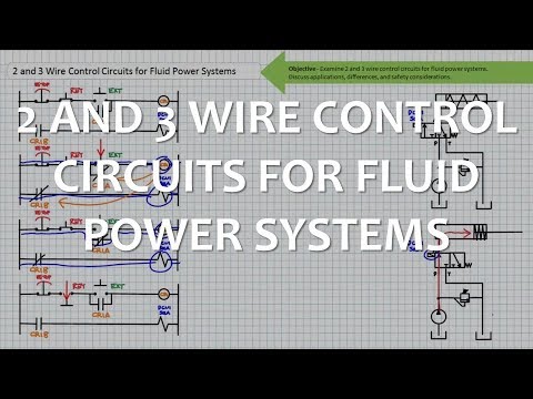
2 and 3 Wire Control Circuits for Fluid Power Systems (Full Lecture