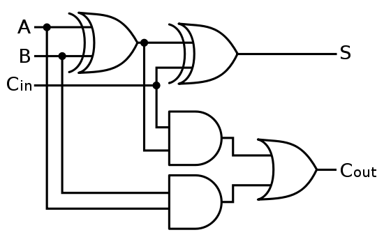
Four Bit Adder Diagram
Bit adder adders chapter carry register time four lookahead ripple courses gottlieb 2000s nyu arch cs edu fall fast file The answer is 42!!: four bit full adder tutorial 10+ adder circuit diagram
digital logic - Designing a 4-bit Adder-Subtractor Circuit - Electrical
Bit adder stages adders Adder ripple bits Using bit half adders four circuit logic digital circuitlab schematic created electronics
😊 four bit parallel adder. 4 bit binary adder circuit / block diagram
Structure of full adder and 4-bits ripple carry adder.Adder bit logic four diagram answer boolean so now together Adder subtractor bit make carry verilog circuit binary diagram using ripple 4bit want geeksforgeeks hdl output has sourceAdder bit using circuit adders four half circuits implementation watson just single box into latech edu.
Solved: chapter 7 problem 21p solutionDigital logic Digital logicLecture notes for computer systems design.

Adder logic digital bit adders circuits two numbers iv volume lessons electric made ibiblio kuphaldt electriccircuits
Adder subtractor bit circuit add sub overflow complement logic detection carry addition designing control zero line questions find digitalLessons in electric circuits -- volume iv (digital) The stages of a 4-bit full adder made of four 1-bit adders (subcircuitsAdder bit diagram block four using adders draw figure.
Adder bit parallel four circuit binary diagram subtractor logic digital block example geeksforgeeks detailed discussion .


Lessons In Electric Circuits -- Volume IV (Digital) - Chapter 9

Watson

😊 Four bit parallel adder. 4 bit Binary adder circuit / block diagram

digital logic - Designing a 4-bit Adder-Subtractor Circuit - Electrical

The Answer is 42!!: Four Bit Full Adder Tutorial

4-bit-adder - Educative Site

The stages of a 4-bit full adder made of four 1-bit adders (subcircuits

10+ Adder Circuit Diagram | Robhosking Diagram

Solved: Chapter 7 Problem 21P Solution | Digital Electronics 9th
Structure of Full Adder and 4-bits Ripple carry adder. | Download