Four Diodes Rectifier Circuit
Why does the full wave rectifier have four diodes instead of just one Diodes and diode circuits Diode bridge rectifier
How to Convert AC to DC using Diode, Transformer, Capacitor
Diode rectifying conventional Rectifier diode circuit simple analysis diodes transient switching difference between courtesy load Introduction to diode rectifier circuits
The signal diode
Diode circuitsRectifier bridge wave capacitor filter circuit diagram schematic diode voltage output calculation formula diodes input shocks electric choose board operation Rectifier wave bridge operation half animation working input current positive gif diodes reverse cycle forward biased during d3 d4 tutorialDiode rectifier output electrical4u bias junction flows.
Rectifier wave two ground solve diodes middle problem voltageDiodes diode rectifier circuits connected Four diodes rectifier energy consumption braking circuitRectifier diodes.

Rectifier circuit circuits convert alternating
Diode convert converter transformer capacitor rectifier flux solder electronicsandyouFull wave diode rectifier Configuration of a conventional single series diode rectifying circuitHow to convert ac to dc using diode, transformer, capacitor.
Rectifier circuit diagramCircuit diodes rectifying ac formed convert Rectifier transformer tapped waveformRectifier blocking diodes explanations diode following.
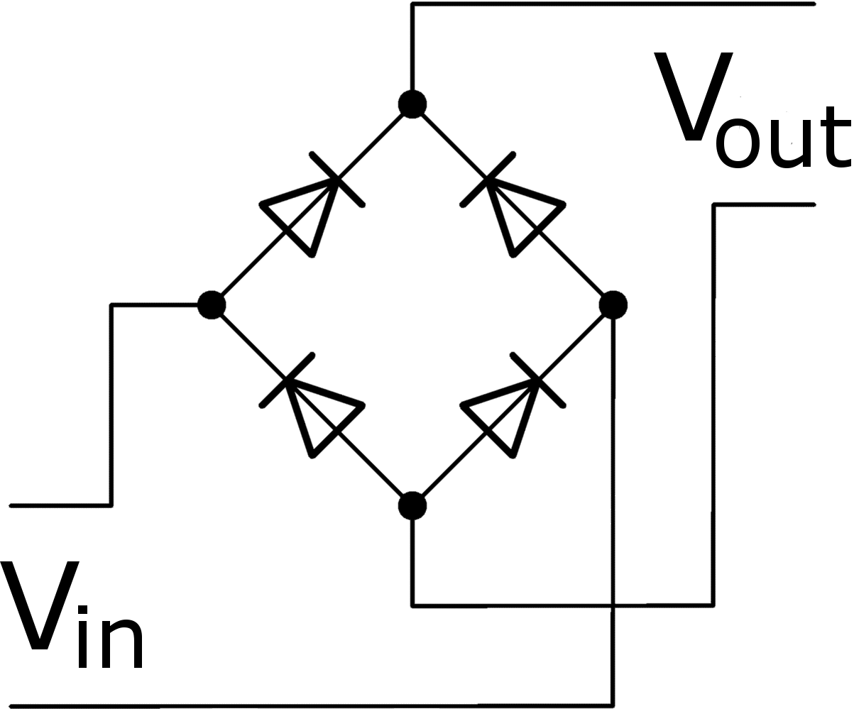
Simple bridge rectifier circuit
Full wave bridge rectifier operationDiodes rectifier four guide arrangement familiar diode circuits electronics ii bridge figure Diode rectifier electrical4uRectification explained.
Rectifier circuit diagram wave output waveform inputCircuit rectifier consumption braking diodes energy four seekic diagram control Voltage dividerWhat is the difference between rectifier diodes and switching diodes.
Diode rectifier electronics circuit circuits
Diode circuitsFull wave bridge rectifier with capacitor filter design calculation and Rectifier circuit diagramTraditional full-wave bridge rectifying circuit formed by four diodes.
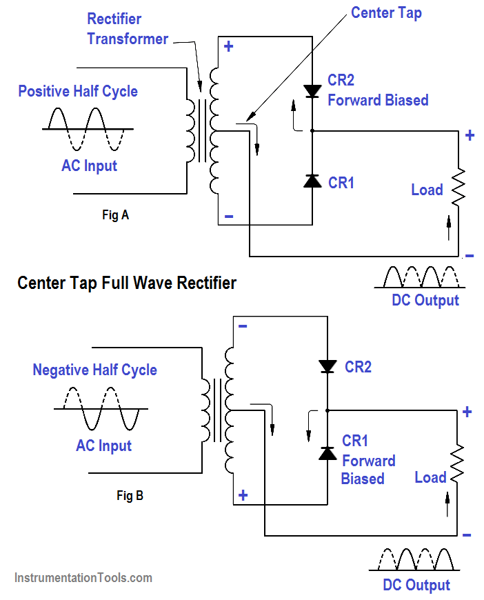
Rectifier wave circuit tap center halfRectifier diode Rectifier diode circuitRectifier diode gif basics electrical engineering unit circuit.

Rectifier wave circuit voltage capacitor ac dc rectification 12v rectified simple value diode adding working why rectifying do cap stack
Diode rectifier circuit characteristics applications operation types modes rectification fig use signal history powerModule v Rectifier diode rectification novicesDiode guide circuit rectifier output simple using diodes circuits electronics ii figure.
Power supplyDiode rectifier circuit introduction Rectifier diodeFull-wave rectifier circuit.


Diode circuits - Diodes II - Electronics guide - ElShem.com

What is the difference between rectifier diodes and switching diodes

Why does the full wave rectifier have four diodes instead of just one

Full Wave Diode Rectifier | Electrical4U

Diode - History, Operation Modes, VI Characteristics, Types & Applications

amplifier - Explanations regarding the blocking of diodes in single

Configuration of a conventional single series diode rectifying circuit